Connect with us today to learn more about our industrial automation solutions—and how to commission them for your application.
What Is an Electromagnetic Clutch Brake Used For?
I can write the introduction, but no source articles or verified expert quotation were provided. Please share a named expert or a source containing their exact words, so I can include an accurate quotation without inventing an attribution.
What an Electromagnetic Clutch Brake Is
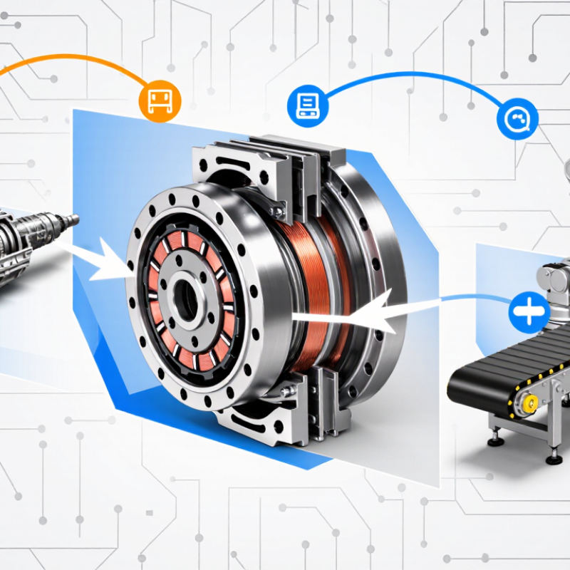
An electromagnetic clutch brake is a machine component that controls motion using magnetic force. It combines a clutch, which connects a motor to a driven shaft, and a brake, which slows or holds that shaft. In many designs, energizing the clutch coil pulls a friction surface into contact and transfers torque. When the clutch releases, a separate brake mechanism can stop the load. Some units use electrical power to apply the brake; others use springs when power is removed.
The name can mislead. Check the design.
Inside the housing, a coil, armature, friction surfaces, and shaft work together. Picture a small packaging conveyor: the motor may keep turning while the clutch engages when a carton reaches a sensor. The brake then helps the conveyor stop at a repeatable position. That matters. Stopping distance still depends on load, speed, friction, and adjustment, so the device is not a substitute for correct system sizing. Heat and wear also affect performance over time, and maintenance intervals vary with operating conditions. A little uncertainty remains until the actual duty cycle is known.
How Its Clutching and Braking Mechanisms Work
What Is an Electromagnetic Clutch Brake Used For?
An electromagnetic clutch-brake controls a rotating shaft by connecting it to a drive source, then stopping it when needed. It is commonly used where equipment must start, stop, or index repeatedly, such as packaging lines and printing machinery. Its clutching and braking actions rely on electromagnetic force and friction surfaces.
When current flows through the coil, a magnetic field pulls an armature across a small air gap. This pressure brings the clutch surfaces together, transferring torque from the motor to the shaft. To stop the load, the clutch releases and the brake engages. In many designs, springs press the brake surfaces together when the coil is de-energized; energizing the brake coil pulls them apart. The transition is brief. Exact arrangements vary, so the unit’s design matters.
Timing affects machine accuracy. A conveyor, for example, may need to stop with a package beneath a filling nozzle. The brake absorbs the load’s motion as friction, which creates heat and gradually wears the lining. Heat matters. In practice, stopping distance can shift with load, speed, temperature, and wear. That detail is easy to overlook. Regular inspection and correct sizing help maintain repeatable operation, though real installations may need adjustment after testing.
What Functions It Performs in Machinery
An electromagnetic clutch-brake controls when a shaft transmits torque and when it stops. The clutch connects the motor to a load; the brake slows or holds that load when the clutch releases. In a packaging machine, this can start a conveyor, stop it at a sensor, and hold a carton in place for filling. Timing matters. The result depends on load inertia, shaft speed, and the unit’s thermal rating—not just its electrical coil.
The U.S. Department of Energy’s 2014 report, Improving Motor and Drive System Performance, estimates that motor-driven systems account for about 68% of electricity use in U.S. manufacturing.
That figure describes factory-wide energy use, not savings attributable to clutch-brakes. Still, it shows why controlled starts and stops matter in motor-driven equipment. Engineers also check stopping frequency, heat buildup, allowable torque, and air-gap adjustment when specifying a unit.
A brake that is too small may overheat during repeated cycles; an oversized one can add cost and unnecessary stopping force.
One detail is easy to miss: the brake may hold a stationary load, but it should not automatically be treated as a substitute for every machine’s safety system. Configuration and operating conditions matter.
Where Electromagnetic Clutch Brakes Are Used
What Is an Electromagnetic Clutch Brake Used For?
Where Electromagnetic Clutch Brakes Are Used
Electromagnetic clutch brakes appear in machines that must start, stop, or position moving parts quickly. In packaging lines, they can control film rollers as bags are formed and sealed. A clutch connects the drive; a brake slows or holds the load. Timing matters. A small delay can leave a label crooked or a package partly sealed.
Printing presses and paper-converting equipment use these units to manage rolls and feed mechanisms. On a cut-to-length line, the brake can stop material at a set point before a blade moves. Machine tools may use them for indexing tables or controlling auxiliary shafts. These applications often involve repeated cycles, so heat and wear deserve attention. The actual stopping point may shift as load, speed, or friction changes.
They also serve in textile machinery, winding systems, and automated assembly equipment. A winding machine, for example, may need controlled pauses without letting the spool unwind freely. Not every installation is straightforward. Engineers need to match torque, inertia, cycle rate, and the required stopping behavior to the machine. A unit that works well on a light feed roller may struggle with a heavier rotating load. Real operating conditions can be messier than the specification sheet suggests.
What to Consider When Selecting One
Selecting an electromagnetic clutch brake begins with the machine’s real load, not just motor horsepower. Compare the required torque with the unit’s rated torque, and account for reflected inertia, peak loads, and frequent starts. A conveyor carrying uneven packages may need more stopping capacity than its motor rating suggests. Measure carefully.
Cycle rate is easy to underestimate. Estimate stops per minute and the energy absorbed during each stop, then check the brake’s thermal capacity. Heat matters. Excessive heat can shorten service life or cause inconsistent stopping. Faster is not always better: a very abrupt stop may jolt the load, while a slow stop may miss the required position. Test with the actual load when possible.
Check the supply voltage, shaft dimensions, mounting space, and wiring before ordering. Dust, moisture, and ambient temperature can also affect the enclosure and cooling needs. Confirm whether the assembly must release or stop the load when power is lost. One detail worth revisiting is stopping accuracy; calculations may look convincing, yet the machine can behave differently under changing loads. A practical selection leaves room to verify performance during commissioning.
What Is an Electromagnetic Clutch Brake Used For?
Energy to dissipate per stop increases with the square of rotational speed. This example assumes a rotating inertia of 0.01 kg·m²; actual requirements depend on the load and system design.
When selecting a clutch brake, consider the load inertia, operating speed, stops per hour, required stopping time, and the unit’s allowable energy per stop and thermal capacity.
Related Posts
-
Top Electromagnetic Clutch Brake Suppliers Worldwide?
-
Top Magnetic Clutch Brake Suppliers Worldwide
-
Best China Magnetic Clutch Brake Manufacturer?
-
Top China VFD Controller Manufacturers How to Choose?
-
Discover How China is Revolutionizing Global Markets with Best 220v VFD Single Phase Solutions
-

Top 10 Benefits of Using VFD Controllers in Industrial Applications