Connect with us today to learn more about our industrial automation solutions—and how to commission them for your application.
7 Tips for Choosing the Right EMI Filter for VFDs
Variable frequency drives (VFDs) improve motor control, but their fast switching can create conducted electrical noise. That noise may disturb nearby sensors, communication lines, or control equipment. The scale matters: the International Energy Agency’s 2011 report, Energy-Efficiency Policy Opportunities for Electric Motor-Driven Systems, estimated that motor-driven systems use about 45% of global electricity. That figure describes energy use, not interference, but it shows how widely motor systems are deployed.
Choosing an emi filter for vfd applications takes more than matching a current rating. The filter must suit the drive’s voltage, operating current, switching behavior, and installation conditions. Cable length and grounding also matter. IEC 61800-3 sets EMC requirements for adjustable speed electrical power drive systems, offering useful context for system-level compliance. A filter alone, however, cannot guarantee a compliant installation.
Small details count. A filter mounted far from the drive may leave noisy cable sections exposed. Poor bonding can undermine an otherwise suitable component. And a filter that works in one cabinet may perform differently in another. That part is easy to underestimate. The practical answer depends on the complete setup, including the motor cable, enclosure, and grounding path. These seven tips focus on the checks that help engineers compare filters, avoid common selection mistakes, and verify performance in the actual installation. Not every installation is textbook-perfect; careful testing may still reveal something the specification sheet missed.
Map the Installation to IEC 61800-3 EMC Categories C1–C4
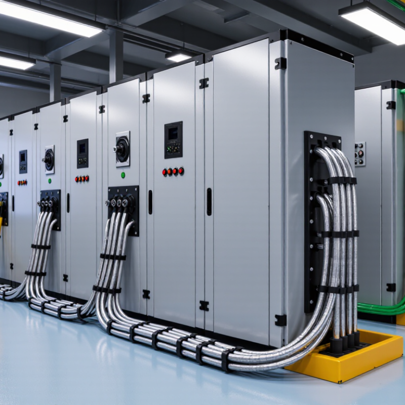
Map the installation before choosing an EMI filter. IEC 61800-3 categories describe the drive system’s EMC environment, not the filter alone. C1 and C2 apply to first-environment installations, such as locations connected to public low-voltage networks. C3 is intended for the second environment, typically industrial sites, with equipment rated below 1,000 V. C4 covers second-environment systems rated at 1,000 V or more, 400 A or more, or considered complex. Check the drive documentation and installation conditions; a voltage rating alone may not settle the category.
Tip: For C1 or C2, check whether the drive serves a home, office, or similar location. C2 equipment needs professional installation and commissioning. Keep filter leads short, bond the filter enclosure securely to the mounting plate, and follow the drive maker’s wiring instructions. A painted panel can interrupt bonding. Easy to miss.
Tip: For C3, review the specified motor-cable length, cable shielding, and grounding method. For C4, treat the installation as a coordinated system. Document cable routes, protective bonding, and any required EMC plan. Select a filter with suitable current and voltage ratings, then verify its attenuation data against the drive’s emissions. A larger filter is not automatically better. I would also check leakage current and upstream protection, because a filter that meets an emissions target can still create installation problems. Category assumptions deserve a second look before purchase.
Set the Conducted-Emission Test Band: 150 kHz–30 MHz
A VFD’s conducted-emission test should span 150 kHz to 30 MHz, rather than focus only on its switching frequency. That is a 200:1 frequency range. IEC 61800-3:2022 defines EMC requirements for adjustable-speed drive systems, while CISPR 11:2015+A1:2016 provides limits and measurement methods for relevant equipment categories. Check which category and installation environment apply before comparing results; the applicable limits can differ.
Use a line impedance stabilization network and scan both line and neutral with the drive operating under representative conditions. Record the motor-cable length, load, grounding arrangement, and switching frequency: each can shift the measured peaks. Look closely at the low end of the band, where drive input stages can produce troublesome emissions, and at narrow peaks that may disappear in a broad average. Small details matter. Compare the filter’s attenuation curve with the measured spectrum, including both common-mode and differential-mode noise. Then verify the result with the intended wiring layout. A quiet bench result can mislead; cable routing in a real cabinet is easy to underestimate.
Match Filter Voltage, Phase, and Current Ratings to the VFD
Start with the VFD’s input nameplate, not its motor output rating. A 480 V, three-phase drive needs a filter rated for that line voltage and phase arrangement. A single-phase filter is not an equivalent substitute. Check the filter’s maximum continuous voltage, frequency, and wiring diagram; line-to-line voltage and grounding details matter. Easy to miss. In a retrofit, verify the actual panel supply, since voltage can vary during operation.
Size current using the drive’s input-current rating at the expected load, then account for any manufacturer-stated derating at cabinet temperatures. Do not select a filter solely from motor full-load amps: input current, overload duty, and heat can change the requirement. Keep the filter’s continuous-current rating at or above the drive’s input current, and check inrush and leakage current. The U.S. Department of Energy’s 2014 report, Improving Motor and Drive System Performance, estimates that motor systems use about 68% of U.S. industrial electricity. That figure gives useful context, not a filter-sizing rule. Check the actual wiring arrangement, filter placement, and protective-earth bonding against the equipment documentation.
Choosing an EMI Filter for a VFD: Match Current Ratings
Example 400 V, three-phase selection: the filter current rating is chosen above 125% of the VFD’s rated input current. Confirm that the filter’s voltage and phase match the supply and VFD, and check the manufacturer’s derating guidance. The 25% margin is illustrative, not a universal requirement.
Review IEC 61800-5-1 Requirements for Protective-Earth Currents Above 3.5 mA
7 Tips for Choosing the Right EMI Filter for VFDs
When selecting an EMI filter for a variable frequency drive, check its protective-earth current, not only its attenuation rating. IEC 61800-5-1:2022 treats currents above 3.5 mA as requiring additional protective measures. That threshold matters. A filter’s capacitors can send current to earth, and long motor cables may add to the installation’s leakage. IEC 60990:2016 describes methods for measuring touch current and protective-conductor current; use the applicable method rather than relying on a catalogue estimate.
For currents above 3.5 mA, IEC 61800-5-1 requires suitable safeguards. Depending on the installation, these can include a suitably rated protective-earth connection or measures that address loss of protective-conductor continuity. Confirm the exact requirements for the drive, filter, and local installation rules. In practice, check the filter’s stated earth-current value, supply voltage, and wiring instructions, then verify the assembled system under operating conditions. A clamp meter reading alone may not reflect the standard’s measurement method.
Keep the PE path short and secure. Record the measured value. I would not assume two filters with similar attenuation create the same earth-current burden; their internal capacitance and the connected cable lengths can differ. Leave room in the panel for the required conductor arrangement, and document how continuity will be checked during maintenance. One detail is easy to miss: filter selection affects both EMC performance and protective-earthing design.
Verify Filter Attenuation with the Installed Cable and Drive Setup
A filter’s attenuation curve is only a starting point. Its published results may come from a test fixture that differs from your VFD installation. Check the drive’s switching frequency, input wiring, motor-cable length, and grounding arrangement. These details can shift the noise profile. Small changes matter.
Test the filter with the actual drive and cable setup whenever practical. Keep cable routing and bonding consistent with the intended installation. Measure conducted emissions at the input using suitable test equipment and a qualified procedure. A current probe can also help identify noise on the motor cable. Check both common-mode and differential-mode behavior; one may improve while the other barely changes. That can be frustrating. Compare readings before and after fitting the filter, across relevant operating speeds and loads. Confirm that the test setup is safe, repeatable, and documented. If the results differ from the filter data, inspect lead length, grounding connections, and nearby wiring before assuming the filter is faulty. Field measurements are imperfect, too. Note the limitations, then use the evidence to guide the next adjustment.
7 Tips for Choosing the Right EMI Filter for VFDs - Verify Filter Attenuation with the Installed Cable and Drive Setup
| Tip | Selection Dimension | What to Check | Practical Selection or Verification Guidance |
|---|---|---|---|
| 1 | Match the electrical ratings | Supply voltage, number of phases, frequency, and continuous current rating. | Choose a filter whose voltage and phase configuration match the VFD supply. Its current rating must cover the drive’s input current under the actual operating conditions; apply the filter manufacturer’s temperature and installation derating instructions. |
| 2 | Confirm the required emissions category | The applicable installation environment, emissions standard, and equipment category. | Identify the applicable requirements before selecting a filter. Limits and test conditions differ by product category, environment, and installation, so a filter’s stated compliance or attenuation should not be treated as proof that the complete drive installation complies. |
| 3 | Check leakage current and protective devices | Filter leakage current, protective-earth arrangements, and any residual-current device (RCD) requirements. | Review the filter and VFD documentation together. EMI filters use capacitors connected to protective earth and can contribute to leakage current; confirm that the installation’s earthing and protective-device arrangements are suitable for the total system. |
| 4 | Include the actual motor cable | Cable type, length, shielding, routing, and connection to the motor and drive. | Use the cable arrangement intended for the final installation when assessing emissions. Long motor leads and cable routing can affect high-frequency behavior; keep motor and input cables routed as specified by the drive manufacturer, and terminate cable shields with a suitable low-impedance connection at the designated points. |
| 5 | Plan filter placement and bonding | Distance from the drive, mounting surface, protective-earth bond, and conductor layout. | Install the filter close to the VFD supply input, following the manufacturer’s instructions. Keep connections short and direct, make the required low-impedance bond to the mounting plate or protective earth, and separate filtered and unfiltered wiring to reduce coupling around the filter. |
| 6 | Distinguish input EMI filtering from output filtering | Whether the concern is conducted emissions on the supply side or motor-side voltage and cable effects. | A line-side EMI filter is intended to reduce conducted interference returning toward the supply. It is not a substitute for a motor-output dv/dt or sine-wave filter; select output equipment separately if required by the motor, cable, or drive manufacturer. |
| 7 | Verify attenuation in the installed setup | Measured emissions with the actual drive, filter, cable, grounding, operating state, and test arrangement. | Use the applicable emissions test method and measure the complete installation. Compare results with the relevant limits across the specified frequency range. Published insertion-loss data is obtained under defined test conditions and may not predict performance in a different cabinet or cable layout. |
Note: Final filter selection and compliance verification depend on the VFD documentation, applicable standards, and the complete installed system.
Related Posts
-
China Top EMI Filter for VFD Manufacturers and Suppliers
-
Best EMI Filters for VFD Applications What You Need to Know
-

Top 5 Tips for Choosing the Best AC Servo Drive Options?
-
7 Best 220V VFDs for Single Phase Motors
-
What Is a 220V VFD Single Phase and How Does It Work?
-
How to Choose the Right Single Phase AC Drive