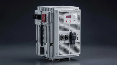
China Top EMI Filter for VFD Manufacturers and Suppliers

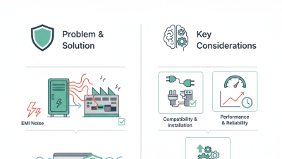
Choosing the right emi filter for vfd requires more than comparing product prices or catalog dimensions. A filter must control conducted emissions without restricting motor performance, increasing leakage current, or creating unexpected resonance. In a factory, these details become visible quickly: a control screen may flicker, a sensor may lose its signal, or a nearby communication cable may report intermittent faults.

Henry W. Ott, a respected electromagnetic compatibility engineer, wrote, “The best way to solve EMC problems is to prevent them in the first place.” His advice remains highly relevant to variable frequency drive installations. Good suppliers evaluate the complete system, including input voltage, drive power, switching frequency, cable length, grounding method, and motor configuration. They should also provide clear electrical ratings, insertion-loss data, leakage-current information, and suitable testing evidence.

China has become an important manufacturing base for EMI filters, offering broad product ranges and competitive engineering support. However, not every supplier provides the same level of technical reliability. Some specifications appear impressive but lack detailed test conditions. That is a weakness worth noticing.

A dependable emi filter for vfd should fit the application, not merely match a model number. Engineers should review thermal behavior, enclosure conditions, installation space, and compatibility with applicable EMC requirements, such as IEC 61800-3. Practical experience matters here. A filter that performs well in a laboratory may behave differently beside long motor cables and imperfect grounding.

This guide examines leading Chinese manufacturers and suppliers, their technical capabilities, product documentation, customization services, and quality-control practices. The comparison is useful, but not absolute. Every installation still deserves careful validation.
China Top EMI Filter for VFD Manufacturers and Suppliers

What Is an EMI Filter for Variable Frequency Drives?

What Is an EMI Filter for Variable Frequency Drives?

An EMI filter is an electrical device that reduces unwanted electromagnetic noise from a variable frequency drive (VFD). The drive rapidly switches voltage to control motor speed. Those fast pulses can travel through power cables and radiate into nearby equipment. A properly selected filter limits conducted and radiated interference, helping control systems operate more reliably.

Most VFD filters use capacitors, inductors, or a combination of both. They suppress common-mode noise and differential-mode noise along the supply path. Filter performance depends on drive current, voltage, switching frequency, cable length, and installation conditions. In field projects, a filter that works well on a test bench may perform differently inside a crowded control cabinet. That is an important limitation.

Tips: Install the filter close to the VFD input terminals. Keep input and output cables physically separated. Use short, wide grounding connections. Select a filter with a current rating above the drive’s continuous input current. Check leakage current before connecting it to a residual-current protection system. Poor cable routing can weaken an otherwise excellent filter.

Experienced manufacturers and suppliers should provide electrical specifications, wiring diagrams, attenuation data, and application guidance. They should also explain whether the filter suits shielded motor cables and harsh industrial environments. Do not choose only by price. A small mismatch can create heat, nuisance trips, or recurring interference. Testing under actual load remains the most dependable verification.

What Is an EMI Filter for Variable Frequency Drives?

An EMI filter reduces high-frequency conducted noise generated by the VFD switching stage and helps prevent interference from travelling through the power supply. The chart shows a representative insertion-loss profile across the 150 kHz–30 MHz conducted-emission measurement range. Actual performance depends on filter design, installation, cable length, grounding, load, and operating conditions.

Reference engineering profile: higher attenuation indicates greater reduction of unwanted conducted noise at the measured frequency.

How EMI Filters Control Interference in VFD Systems

China Top EMI Filter for VFD Manufacturers and Suppliers

How EMI Filters Control Interference in VFD Systems

A variable frequency drive creates fast voltage changes while controlling motor speed. These switching edges can produce common-mode and differential-mode noise. The noise may travel through power cables, motor leads, and protective earth connections. An EMI filter controls this interference with inductors and capacitors. Inductors resist high-frequency current changes. Capacitors redirect unwanted noise toward the appropriate return path. This reduces conducted emissions before they reach nearby equipment.

Filter performance depends on installation quality. A suitable current rating prevents overheating during continuous operation. The filter should sit close to the VFD input terminals. Long wires between the filter and drive can act like antennas. Poor grounding may also weaken the result. Motor cable length, switching frequency, leakage current, and enclosure design require careful review. A filter is not a cure-all. Field testing sometimes exposes problems that calculations miss.

Tips: Keep input and motor cables separated. Use short, wide grounding connections. Check the filter’s voltage, current, and leakage specifications. Measure noise with appropriate test equipment, rather than trusting appearance alone. Ferrite components may help in some cases, but they cannot replace correct filter selection. Recheck the system after installation. Small wiring changes can produce surprisingly different results.

Key Specifications for Selecting a VFD EMI Filter

China Top EMI Filter for VFD Manufacturers and Suppliers

Key Specifications for Selecting a VFD EMI Filter

Selecting a VFD EMI filter starts with matching the drive’s electrical ratings. Check the input voltage, phase configuration, and continuous current. A filter rated below the drive current may overheat during acceleration. Leave a practical margin, but avoid excessive oversizing. It can increase cost and leakage current.

Attenuation performance matters across the inverter’s noise range. Review the insertion-loss curve, not only one impressive test value. Most applications need strong suppression from 150 kHz to 30 MHz. Confirm the filter’s operating frequency and impedance conditions. Common-mode and differential-mode performance should both be considered. They reduce interference through power cables and grounding paths.

Leakage current is easy to overlook. Excessive leakage may trigger protective devices or create unwanted chassis current. Check the manufacturer’s test method and installation diagram. Environmental details also matter. Confirm the temperature range, humidity resistance, enclosure rating, terminal size, and cooling clearance.

During commissioning, measure conducted emissions with the final cable length and motor load. Laboratory results may change in a crowded control cabinet.

I have seen a suitable filter underperform because the grounding path was too long. That mistake is common.

Keep motor cables shielded, short where possible, and separated from signal wiring.

For suppliers in China, request traceable test reports, batch inspection records, and clear application guidance before approval. Datasheets help, but field evidence matters more.

China’s Leading EMI Filter Manufacturers and Suppliers

China’s leading EMI filter manufacturers and suppliers are responding to stronger demand for reliable VFD protection. Grand View Research estimates that the global variable frequency drive market will expand steadily through 2030, supported by industrial automation and energy-efficiency projects. This growth increases the need for filters that control conducted noise, leakage current, and motor-cable interference.

Experienced suppliers usually begin with the application, not a standard catalog number. They check voltage, rated current, switching frequency, enclosure space, and cable length. A suitable filter may include three-phase input terminals, shielding, thermal protection, and low-impedance grounding. The filter must also support the installation requirements of IEC 61800-3. Small details matter. A short ground path can reduce unwanted emissions significantly.

MarketsandMarkets has identified rising electromagnetic compatibility requirements as a major driver for the EMI shielding and filtering industry. Chinese manufacturers increasingly support this demand with customized testing, sample validation, and batch traceability. Technical documents should show insertion-loss curves, leakage-current values, temperature limits, and applicable test conditions. Some suppliers still present impressive laboratory results without enough installation guidance. That deserves careful review. A filter is not a magic shield. Poor cabinet bonding, excessive cable length, or incorrect grounding can weaken an otherwise capable design. Reliable suppliers therefore combine production experience with verification before shipment.

China Top EMI Filter for VFD Manufacturers and Suppliers - China’s Leading EMI Filter Manufacturers and Suppliers

Filter Category Typical VFD Application Nominal Voltage Typical Current Range Electrical Configuration Typical Frequency Range EMI Performance Installation Method Common Compliance Requirements Selection Considerations
Single-Phase Input EMI Filter Compact drives, small pumps, fans, conveyors, and machine-control equipment 110–120 V AC or 220–240 V AC Approximately 3–30 A Single-phase, two-line input with protective earth 50/60 Hz power frequency; high-frequency attenuation for conducted noise Designed to reduce common-mode and differential-mode interference generated by switching power electronics DIN rail, chassis mount, or panel mount IEC/EN 60939, IEC/EN 61800-3, and applicable EMC requirements Confirm input voltage, rated current, leakage current, enclosure space, and earthing arrangement
Three-Phase Input EMI Filter Industrial VFDs used for motors, compressors, HVAC systems, machine tools, and material-handling equipment 200–240 V AC or 380–480 V AC Approximately 3–300 A Three-phase, three-line input with protective earth; neutral connection is normally not required 50/60 Hz power frequency; broadband conducted-noise suppression Reduces radio-frequency noise on the input power lines and helps control conducted emissions Chassis mount or cabinet mount IEC/EN 60939, IEC/EN 61800-3, and local electrical safety regulations Choose a filter with a current rating at least equal to the drive input current and verify phase configuration
Three-Phase Plus Neutral Filter VFD panels and systems where a neutral conductor is routed through the same electromagnetic compatibility boundary Typically 380–480 V AC line-to-line Approximately 10–100 A Three-phase plus neutral and protective earth 50/60 Hz power frequency with high-frequency interference attenuation Provides filtering for phase conductors and the neutral path when required by the system design Cabinet or panel mount IEC/EN 60939 and system-level EMC requirements Use only when the neutral conductor must pass through the same filter; check neutral current and wiring layout
High-Current VFD EMI Filter Large pumps, fans, extruders, compressors, cranes, and high-power motor drives 380–690 V AC Approximately 100–1,000 A Three-phase input, usually with a dedicated protective-earth connection 50/60 Hz power frequency; high-frequency suppression depends on filter design and installation Used to reduce conducted emissions from high-power switching converters Floor-standing cabinet, busbar, or heavy-duty chassis mount IEC/EN 60939, IEC/EN 61800-3, and applicable high-voltage installation standards Evaluate thermal dissipation, short-circuit withstand, busbar clearance, service access, and fault protection
Output Motor-Side EMI Filter Motor cable noise control, sensitive installations, long motor cables, and systems requiring reduced radiated emissions Matched to the VFD output voltage Matched to or above the VFD output current Three-phase output filter installed between the drive and motor Motor switching waveform frequency; performance depends on carrier frequency and cable characteristics May reduce common-mode voltage, motor-cable emissions, and stress on motor insulation Chassis mount or cabinet mount near the VFD or motor cable exit IEC/EN 61800-3 and applicable motor-drive EMC requirements Check compatibility with PWM output, carrier frequency, motor cable length, voltage drop, and drive instructions
RFI Feed-Through Filter Control cabinets, automation panels, measurement areas, and installations with strict radio-frequency limits Commonly 250 V AC or 440–480 V AC, depending on configuration Typically 1–100 A Feed-through terminals with capacitive and inductive filtering elements Broad radio-frequency attenuation range; exact performance depends on circuit and enclosure design Useful for controlling high-frequency interference crossing a cabinet wall or equipment boundary Panel feed-through or bulkhead mount Applicable EMC, insulation, creepage, and clearance requirements Maintain a clean separation between input and output wiring and ensure low-impedance bonding to the enclosure
Compact DIN-Rail EMI Filter Small VFD control panels, OEM machinery, building automation, and space-limited electrical cabinets 230 V AC or 400 V AC, depending on the model Approximately 3–25 A Single-phase or three-phase configuration 50/60 Hz power frequency with high-frequency noise attenuation Provides practical conducted-EMI reduction in compact installations Standard DIN-rail mounting IEC/EN 60939 and applicable EMC requirements Verify rail compatibility, terminal size, ventilation, derating, and separation from noisy output cables
Custom Cabinet-Integrated Filter OEM equipment, export machinery, multi-drive systems, and application-specific control cabinets Specified according to the complete electrical system Specified according to total input current and drive loading Single-phase, three-phase, multi-drive, or combination filtering Selected according to the required conducted and radiated emission limits Can be coordinated with reactors, shielded cables, grounding, and cabinet layout for system-level EMC control Integrated cabinet assembly, backplate mount, or busbar system IEC/EN 61800-3, IEC/EN 60204-1, IEC/EN 60939, and destination-market requirements Provide the VFD model class, system voltage, current, cable lengths, enclosure layout, and target EMC environment

How to Evaluate VFD EMI Filter Quality and Support

China Top EMI Filter for VFD Manufacturers and Suppliers

When evaluating a VFD EMI filter, inspect the application before comparing catalog ratings. A filter must match input voltage, current, frequency, and drive topology. Check conducted-emission data across the expected load range. Do not trust a single laboratory graph. Cable length, grounding, enclosure design, and switching frequency can change results significantly. During field commissioning, I measure noise at the power input and motor terminals. A quiet panel is not always a compliant installation. Important distinction.

Quality also appears in construction details. Look for marked terminals, secure barriers, thermal ratings, and documented leakage current. Magnetic cores should support continuous current, not occasional peaks. Capacitors need suitable safety classifications and clear life expectations. Ask for impulse, temperature-rise, vibration, and insulation tests. Traceable reports are more useful than vague claims such as “high performance.” I have seen filters pass bench tests yet overheat inside crowded cabinets. Airflow matters. So does terminal torque.

Support should include wiring diagrams, grounding guidance, installation review, and responsive technical answers. A capable supplier explains what the filter cannot solve, including radiated noise or poor motor-cable shielding. Request samples when the drive system is unusual. Test them with the actual cable, motor, and enclosure. Keep records of line current, leakage current, and emissions before and after installation. One practical weakness remains: many evaluations ignore maintenance conditions. Dust, loose terminals, and altered cable routes can quietly reduce performance. That deserves a place in the acceptance plan.

Learn More

Connect with us today to learn more about our industrial automation solutions—and how to commission them for your application.