
Beckhoff TwinSAFE Setup Guide for KEB Drives with TwinCAT Software

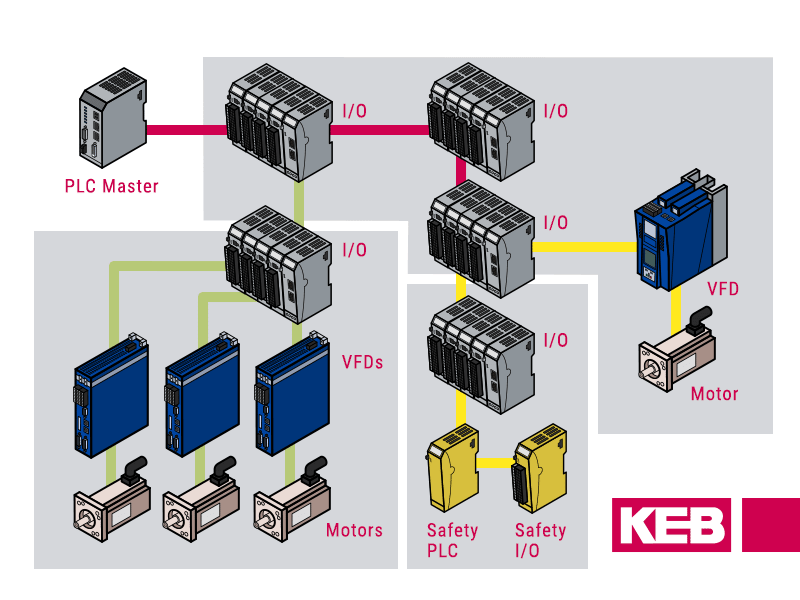
Looking to implement a robust safety system? This Beckhoff TwinSAFE setup guide will show you how to configure a safety PLC program using TwinCAT software and establish Fail-Safe over EtherCAT (FSoE) communication with a KEB S6A drive. We’ll cover everything from the necessary hardware and software to successfully linking your Beckhoff PLC, safety PLC, KEB safe I/O, and KEB drive.
1. Software and Hardware Requirements
Here is the list of equipment used in this FAQ:
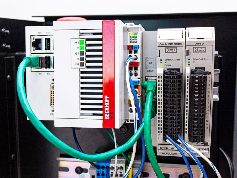
- Beckhoff CX5120 PLC
- Beckhoff EL6910 Safety PLC Module
- Beckhoff EL2904 Digital Output Module
- Beckhoff EL1122 EtherCAT Junction
- TwinCAT v3.1.4024.55 Software
- KEB Combivert S6A SM3 Drive 10S6A32-1100
- KEB Bus coupler 00C6CA1-0100
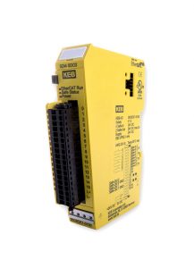
- KEB FSoE Safety SDI4 SDO2 Module 00C6CE1-0100
- KEB USB Serial Adapter 0058060-0040
- COMBIVIS 6 Version 6.7.1.416 Software
When all of the hardware is wired up correctly and the proper software is installed you may begin the next step of creating a project and beginning the PLC programming.
2. Set Up the TwinCAT Program
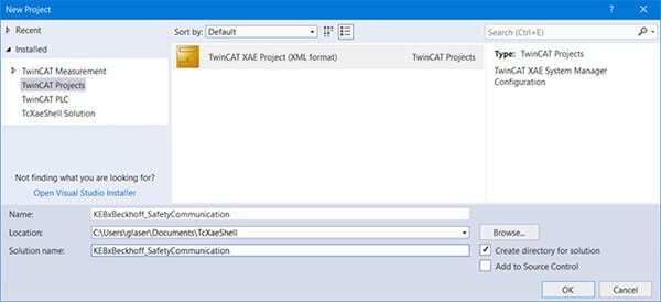
The first thing you want to do is open a new project in TwinCAT software.
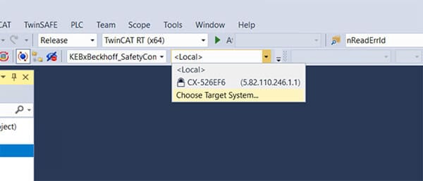
After opening a new project, choose a target system for your application.
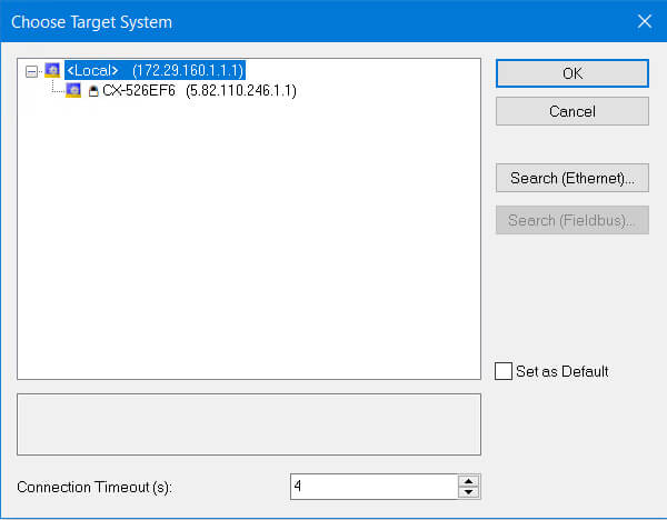
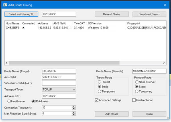
Then you will need to go to “Search (Ethernet)” in order to find the IP address of the PLC port connected to the PC. Ensure the PC’s Ethernet port is in the same subnet as the PLC’s IP address. If the IP is unknown, try “Broadcast Search.” Once your PLC appears, click “Add Route.”
A prompt will appear asking for the username and password. The default username and password are Administrator and 1, respectively. If changed, enter the updated credentials.
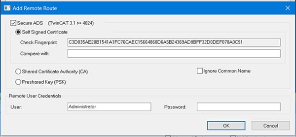
Click “OK” and close the routing window. Select your PLC from the dropdown menu. Ensure the PLC is in “Config Mode” by clicking the blue button shown below and restarting the TwinCAT system in Config Mode.

3. Configure I/O Devices
In this section, we will guide you through the process of adding your devices and configuring them properly for the application.
3.1 Add Devices
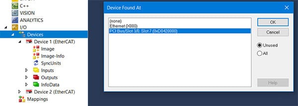
Under I/O, right-click “Devices,” select “Add New Item,” and add “EtherCAT Master.” For this guide, we’ll configure Safety IO modules connected via PCI slots with an EtherCAT junction.
The correct EtherCAT description files must be imported in TwinCAT in order to proceed with using a Safety Module 3 KEB drive. Assuming Combivis 6 is already installed, you can likely find the EtherCAT description files at:
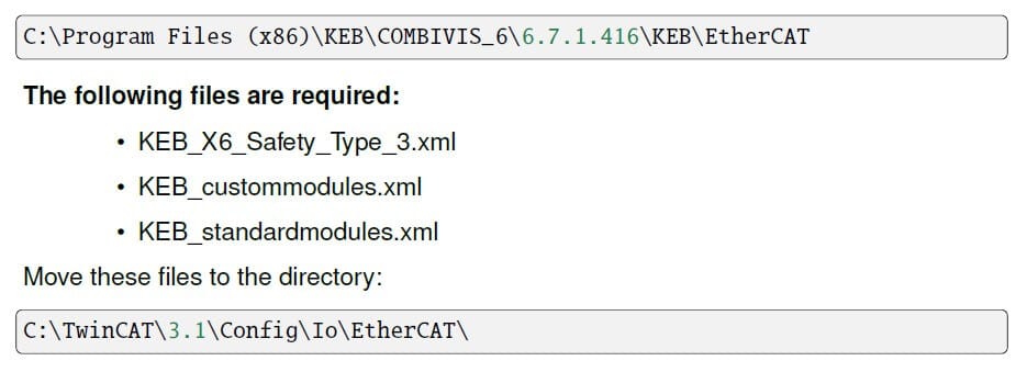
After the files have been moved over to the TwinCAT folder, the main TwinCAT program must be closed and reopened again. The simple “Reload Device Descriptions” in TwinCAT is insufficient.
Reopen the project, right-click on the “EtherCAT Master,” and click “Scan.” (You will only be able to do this in Config Mode)
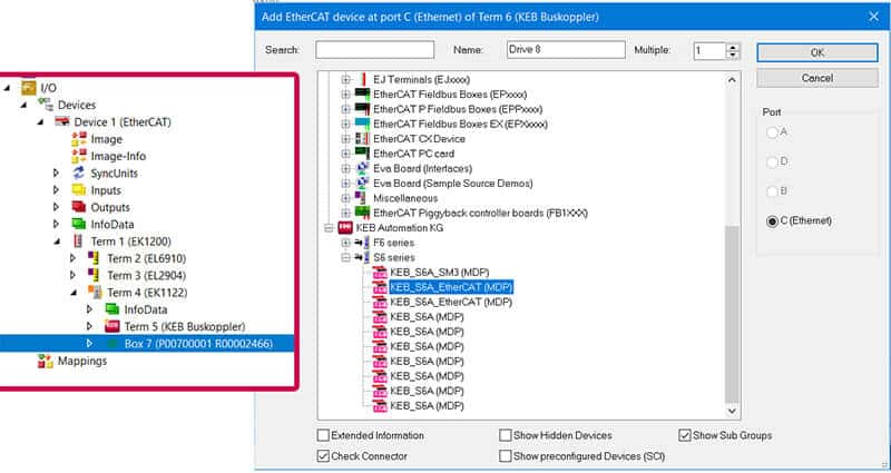
The KEB drive will not be correctly identified in the scan, and will likely show up as something similar to “Box X.” To add the drive, right-click on the item above “Box X” and click “Add New Item.”
For this example, we right-clicked on “Term 5 (KEB Buscoupler),” and selected “Add New Item.” Under the KEB Automation KG folder, select “KEB_S6A_EtherCAT (MDP).” A window will pop up about appending a linked axis, and you can click “cancel,” unless your application requires otherwise.
Once the KEB drive is added, you can delete the “Box X” device.
3.2 Configure I/O Devices
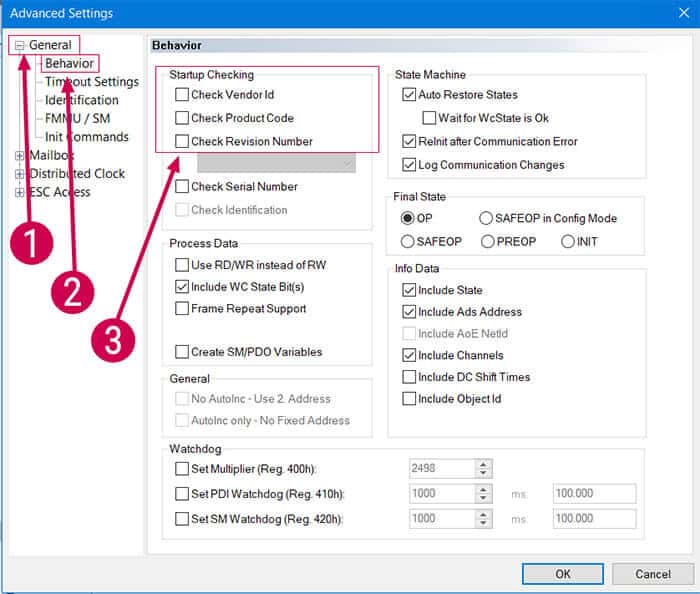
Open the S6A_EtherCAT module and click on the “EtherCAT” tab. Open “Advanced Settings.” In the General/Behavior settings, make sure “Check Vendor ID,” “Check Product Code,” and “Check Revision Number” are all unselected.
Next, click the “Slots” tab in the S6A_EtherCAT module.
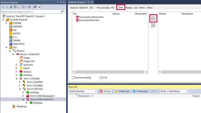
Select the safety module slot (Sicherheits-Modul Slot). A view with available modules should now be displayed on the right side of the window. Select a module description and accept with the “<” button. Make note of the number after “SM3” in the module that you selected. This will be used later as the number of bytes being transferred over the safety process data. In our example, we are using 6 bytes of safety process data.
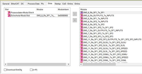
A standard process data description can additionally be mapped in the process data module slot A. For this example, we will use KEB’s “std PD map (S6)” standard process data mapping.
4. Configure Safety
With all the devices added to your TwinCAT project and mapped properly, we can move forward to configure the safety side in TwinSAFE.
4.1 Create and Configure Safety Project
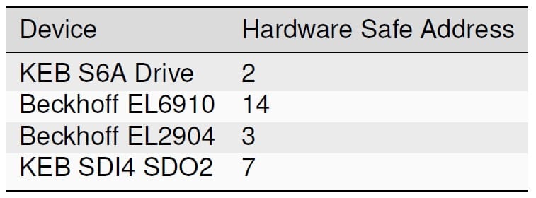
Before safety is configured on the software level, determine each safety address of all of the safety devices used. Most devices have a physical dip switch to configure. Each safety device needs to have a unique safety address.
In this example, the safe addresses are assigned accordingly:
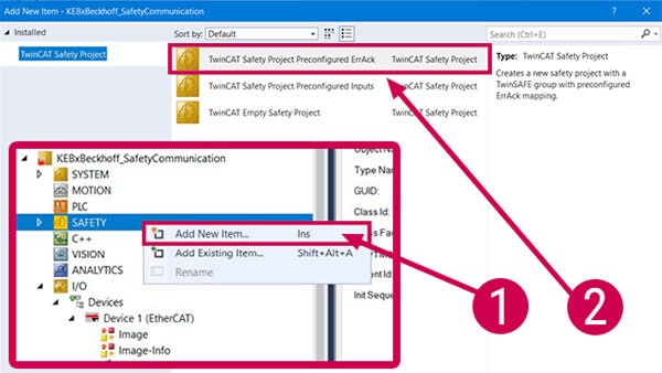
To start configuring safety on the software level, right-click on the “SAFETY” item, and select “Add New Item.” Add a “TwinCAT Safety Project Preconfigured ErrAck” safety project.
Next, select “Target System” under the new safety project.
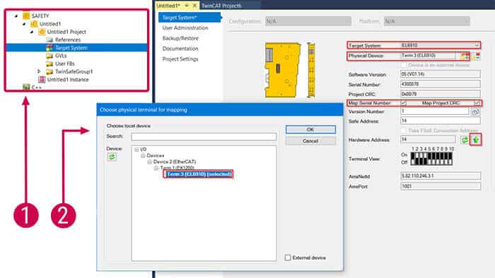
Select your “Target System” and “Physical Device.” We will be using a EL6910. Also, ensure that you check the boxes for “Map Serial Number” and “Map Project CRC.” Select the green “up arrow” next to “Hardware Address” for the software to map the safe address according to the physical DIP switch configuration on the device. Also make sure to click the “save all” icon in the toolbar to save the Target System configuration and the project altogether.
4.2 Create and Configure KEB Drive Safety Project
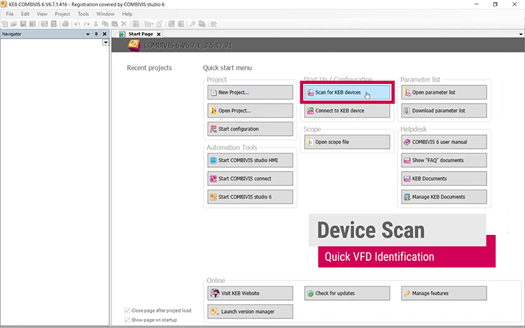
Next, we will open Combivis 6, KEB’s drive software. Once the program is open, click “Scan for KEB devices.”
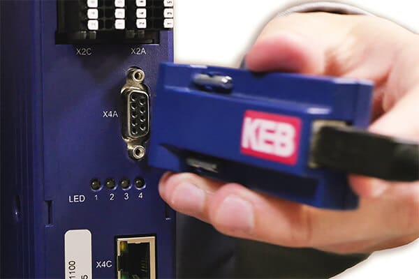
The KEB USB Serial Adapter (0058060-0040) is necessary to program the drive. Plug the serial end of the adapter into the X4A port of the drive, and the USB end into the PC.
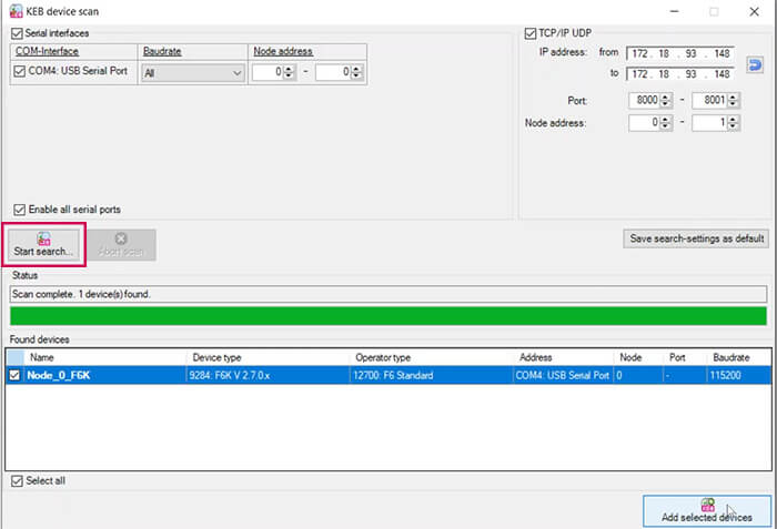
The associated COM port should appear. Once it does, select that COM port and select “Start search.” Once the drive appears, select “Add selected devices.”
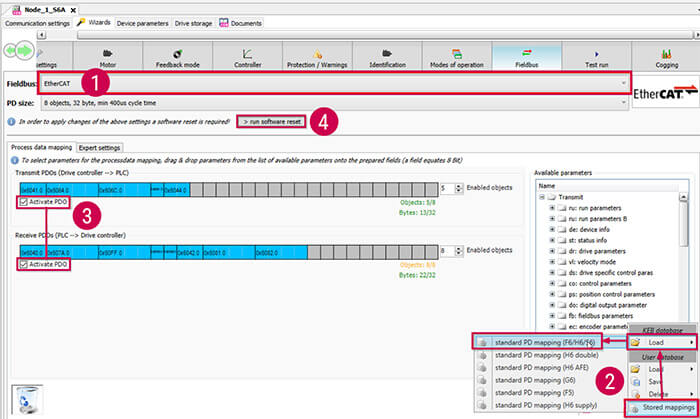
Go to the fieldbus wizard tab. First, select the EtherCAT fieldbus configuration. Second, add “standard PD mapping.” Third, activate PDO for Transmit PDOs and Receive PDOs. Fourth, click “run software reset” to apply the fieldbus changes.
Open the KEB Safety Module in the navigator under the drive. In the top right-corner, log in with your credentials. The default username is ‘1’ and the default password is ‘default’. This default username and password are only used to create new users, and it is not possible to download safety parameters with this login information. More information on safety module users can be found in the “KEB Safety Module Type 3” manual.
Once you are logged in, click the “safe parameterization” tab.
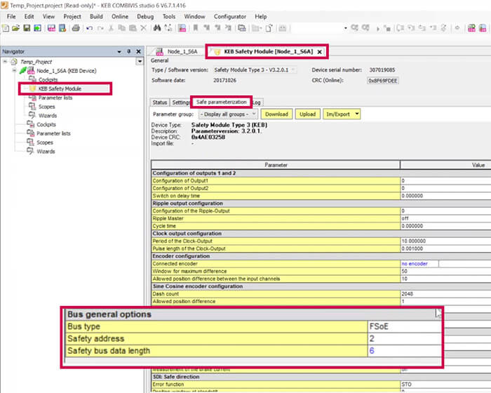
At the very bottom of the “Safe parameterization” tab, you will find “Bus general options.” Select “FSoE” for bus type. Select a unique safety address and select the safety bus data length to match the number of bytes chosen for the safety module slot of the S6A_EtherCAT module in TwinCAT. In this example, the safety address was chosen as 2. The safety process data chosen was “SM3_6_Rx_SF1_Tx_SF1,” so there are 6 bytes of safety bus data.
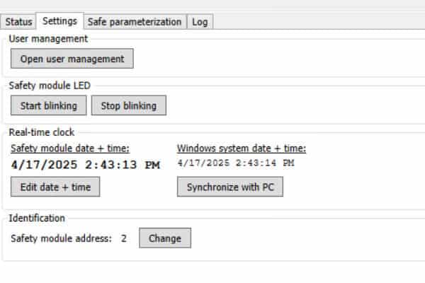
It is also necessary to change the safety module address in the “Settings” tab of the KEB Safety Module to match the safety address chosen in the “Safe parameterization” tab.
After configuring the bus general options, in “Safe parameterization,” click “download” to download the safety configuration to the drive. You must be logged into the safety module and have STO dropped to perform this action.
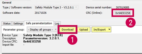
After completing the download, copy the “CRC (Online)” (shown in the image above) to your clipboard. Perform a power cycle to the drive. Remember, when power cycling high voltage, it’s best practice to leave the drive off for 15 seconds to let the capacitors completely discharge before powering back on.
We will now return to TwinCAT.
4.3 Safety I/O Configuration
Under your new TwinSAFE Group in your safety project, right click on “Alias Devices,” and select “Import Alias-Device(s) from I/O-configuration.”
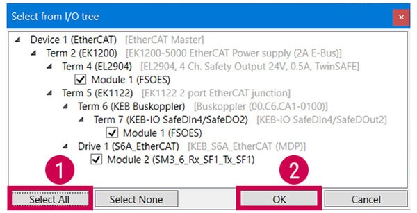
You can select the I/O devices being used in the project, which should be the all the devices shown, and you can “Select All.”
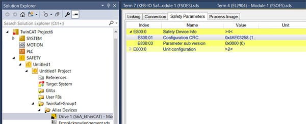
Under the KEB Drive device alias device, and under the “Safety Parameters” tab, expand “Safety Device Info.” Edit the Configuration CRC and paste the Device CRC from Combivis 6 into the Hex entry. Click “OK.”
Configure each of the safety alias devices within each alias device module according how they will be used.
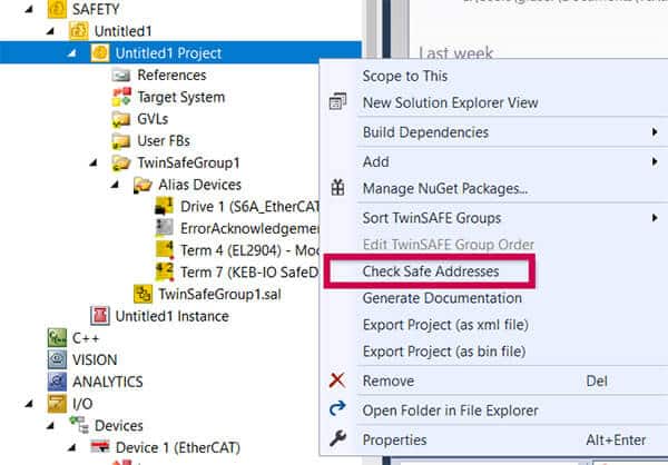
Next, verify their safe addresses by right-clicking on the safety project instance and selecting “Check Safe Addresses.”
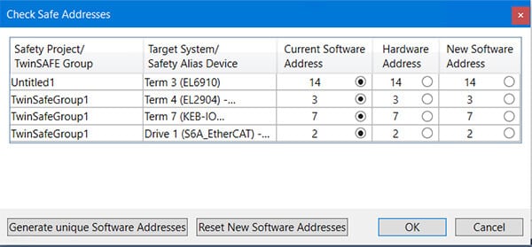
If everything is connected, configured, and communicating properly, you should have all non-zero integers for all three columns in the “Check Safe Addresses” window.
4.4 Create Standard PLC Project
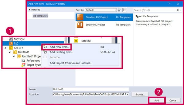
Right-click on the PLC icon in the navigator and select “Add New Item.” Then add a “Standard PLC Project.”
Under “I/O,” open up the “EtherCAT Master” and go to the “EtherCAT” tab. Select “Sync Unit Assignment.”
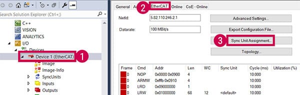
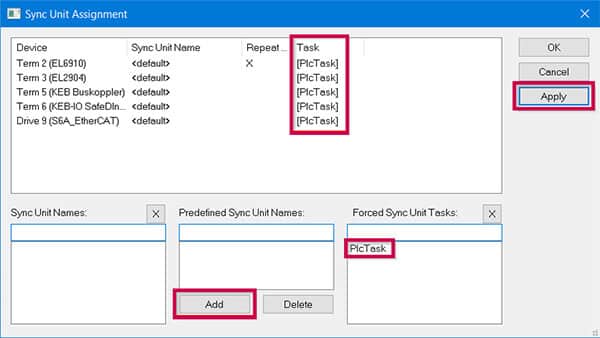
Assign each device the newly created PLC task by selecting the task in “Forced Sync Unit Tasks,” selecting the device, and clicking “Add.” Once all devices have been assigned the task, select “Apply” and then “OK.”
4.5 Create Safety Program in TwinSAFE
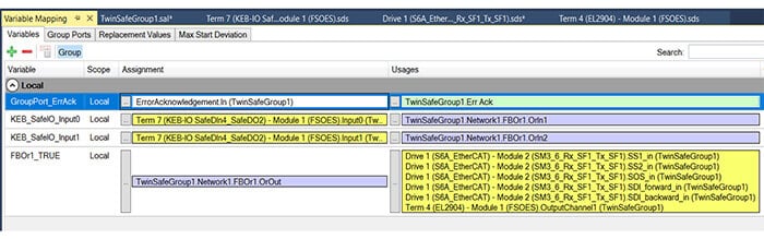
Select “TwinSafeGroup1.sal” in the navigator and create a simple program that utilizes all of the alias devices. As an example, we can use a safeOr function block, and define variables for two inputs and one output. To assign IO to these variables, right-click on any defined variable and select “Go To Linked Element.” A “Variable Mapping” window will open where you can assign the IO to the variables.
Once complete, under the TwinSAFE tab, select “Verify Complete Safety Project,” and address any errors that may occur.

If no errors occur, “Verification Process succeeded” should appear in the lower left corner of the screen. Next, select the “Activate Configuration” button in the top left of the toolbar, and click “OK” on the following two windows. The PLC will now be in run mode.
4.6 Download a Safety Project Data
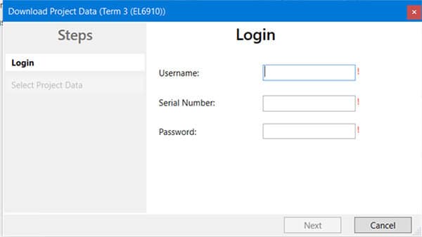
To download the safety project, select “Download Safety Project” under the TwinSAFE tab. A login screen will appear. Enter the username and password of the device chosen in the “target system” of the safety project. In our case, the target system is the EL6910. The default username is Administrator, and the default password is TwinSAFE. The serial number is located on the side of the physical device.
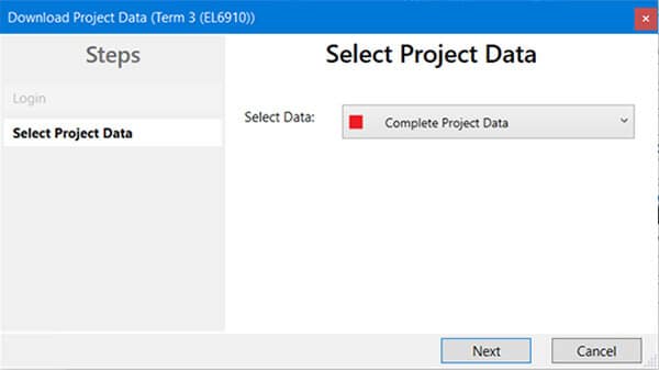
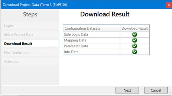
If successfully logged in, you will be prompted to select data being downloaded to the device. You can select “Complete Project Data” and click “next.”
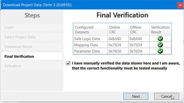
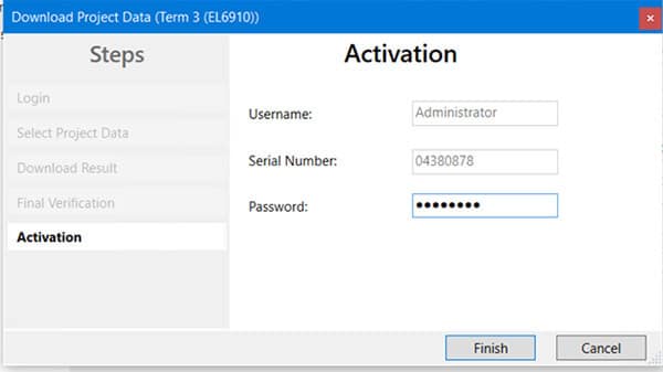
Re-enter the password to activate the safety project and click “Finish.”
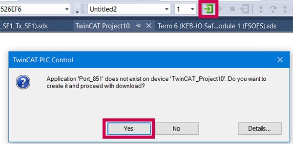
Now, you can login and download the application to the PLC. Once downloaded, click start.
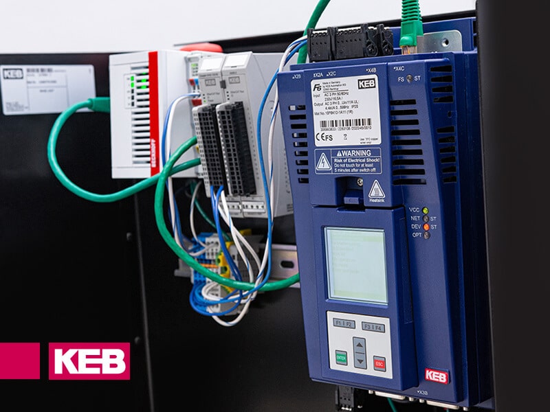
You can monitor the status of the safety project on the drive by observing the LEDS on the KEB drive. The “FS ST” (functional safety status) LED, the “VCC” (24V control card input supplied) LED, the “NET ST” (network status/EtherCAT connection) LED, and “DEV ST” (device status/no errors) LED should all be solid green.
Conclusion
By working through these steps your Beckhoff TwinSAFE setup for safety communication on TwinSAFE over EtherCAT FSoE using a CX5120 PLC and a KEB S6A drive should be complete. As a reminder, whenever you make a change to the program, go offline, or if EtherCAT communication is dropped, you will need to verify and re-download the safety program.
Related Articles
Let's Work Together
Connect with us today to learn more about our industrial automation solutions and how to commission them for your application.
"*" indicates required fields