Connect with us today to learn more about our industrial automation solutions—and how to commission them for your application.
10 Tips for Choosing the Right RF Coaxial Connector
Choosing the right Rf Coaxial Connector is not a minor purchasing decision. It can influence signal loss, impedance stability, shielding, and equipment reliability. A connector may look solid in your hand, yet perform poorly above its rated frequency. Small details matter. Contact geometry, plating, cable size, and mating quality all affect the final result.
Dr. Eric Bogatin, a respected signal-integrity expert, offers a useful principle: “The return path is part of the signal path.” This idea applies directly to coaxial connections. A loose shield, damaged thread, or poorly matched interface can disturb that path. The result may appear as insertion loss, reflections, noise, or unstable measurements. A vector network analyzer can reveal these problems, but only after the connector has already been selected.
This guide presents ten practical tips for choosing a suitable connector. It considers frequency range, impedance, power handling, environmental exposure, mechanical strength, and installation method. It also examines familiar options, including SMA, N-type, BNC, TNC, and MMCX designs. Datasheets deserve careful reading. Marketing language is not enough. Check actual test conditions, mating cycles, and cable compatibility.
There is no universally perfect connector. That is easy to forget. A laboratory setup may need precision, while an outdoor system needs sealing and durability. Cost can also mislead. The cheapest part may create expensive troubleshooting later. Even experienced engineers occasionally overlook torque, adapters, or connector cleanliness. These tips encourage careful comparison, honest testing, and a willingness to question assumptions before committing to one Rf Coaxial Connector.
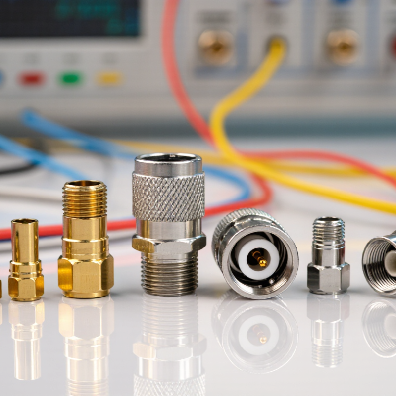
Define the RF Application and Required Frequency Range
Choosing an RF coaxial connector begins with the application, not the connector shape. Define the signal path, operating frequency, impedance, and available space. A connector for a low-frequency control signal may fail in a microwave circuit. Frequency changes electrical behavior.
Write down the lowest and highest operating frequencies. Include harmonics, sidebands, and future upgrades. Check insertion loss, return loss, and voltage standing wave ratio across that full range. A connector rated only at the center frequency can create surprises near the upper limit. Small mismatches matter. They can reduce transmitted power and distort sensitive measurements.
I have seen teams select a connector because it fitted the enclosure. Later, the cable assembly showed unstable readings above several gigahertz. The real problem was an overlooked frequency limit and a poor transition between cable and board. That mistake was avoidable. Confirm the cable diameter, center conductor size, shielding structure, and required bend radius. Then review power handling at the actual frequency and temperature. Mechanical details also matter, especially where technicians reconnect equipment often. A connector with excellent specifications may still be wrong for vibration, moisture, or limited access. I sometimes over-focus on electrical data. That is a weakness. The installation environment deserves equal attention. Record every requirement before comparing connector types, and verify results with network-analyzer measurements when possible.
Match Impedance, Connector Type, and Interface Standards
Tip 1: Confirm impedance before comparing connector shapes. Most RF systems use 50 ohms, while many video systems use 75 ohms. A mismatch can create reflections, standing waves, and unexpected insertion loss. Check the equipment label, cable specification, and test setup. Small mismatch. Big trouble.
Tip 2: Match the connector type to the operating environment. Threaded interfaces usually resist vibration better than push-on designs. A compact board connector may save space but require careful alignment. During installation, I check the mating force and inspect the center contact under magnification. It is a simple habit, but it prevents costly rework. I once trusted a familiar connector without checking its frequency rating. That shortcut was not wise.
Tip 3: Verify the complete interface standard, not only the connector name. Dimensions, gender, keying, coupling method, and allowable tolerances must agree. Standards such as IEC 61169 can help confirm mechanical requirements, while the manufacturer’s drawings should verify exact dimensions. Never assume two similar-looking interfaces will mate safely. They may fit, yet perform poorly.
For high-frequency applications, compare return loss, insertion loss, shielding effectiveness, and maximum operating frequency. Use a calibrated network analyzer when possible. Tighten threaded connectors according to the specified torque, rather than relying on feel. Keep adapters to a minimum. Every extra junction adds another possible failure point. Document the selected interface, impedance, cable type, and test results before production. Calibration records matter. Specification sheets can contain gaps, so independent measurements remain valuable.
10 Tips for Choosing the Right RF Coaxial Connector - Match Impedance, Connector Type, and Interface Standards
| Tip | Selection Dimension | Common Options | Verified Technical Guidance | Recommended Check | Priority |
|---|---|---|---|---|---|
| 1 | Impedance | 50 Ω or 75 Ω | Use 50 Ω for most wireless, test, radar, and high-frequency data systems. Use 75 Ω for many video, broadcast, and cable-distribution systems. Mixing impedances can increase reflections and signal loss. | Confirm the impedance shown on the equipment specification, cable datasheet, and connector drawing. | Critical |
| 2 | Connector family and interface | SMA, BNC, TNC, N, F, SMB, MCX, MMCX, 7/16 DIN | The connector must physically mate with the equipment. Similar-looking interfaces are not automatically interchangeable; thread, bayonet, snap-on, and push-on designs have different mating methods. | Match the exact connector family, gender, coupling mechanism, and mating dimensions. | Critical |
| 3 | Operating frequency | kHz to microwave bands | Connector performance depends on geometry, construction, and assembly quality. A connector suitable at 1 GHz may not provide the same return loss at 18 GHz or higher. | Choose a specified upper frequency above the application’s highest operating frequency and review return-loss data. | Critical |
| 4 | Cable compatibility | Flexible coax, semi-rigid, corrugated, twin-shield | Crimp, clamp, solder, and compression terminations are designed for specific cable diameters, dielectric sizes, braid structures, and center-conductor dimensions. | Compare the connector’s cable-range specification with the cable outer diameter and construction. | High |
| 5 | Interface and dimensional standard | IEC 61169 series, equipment drawings, industry specifications | International connector standards define relevant mechanical and electrical requirements for various connector families. The applicable part depends on the connector type. | Check the applicable IEC 61169 specification, drawing revision, tolerances, and interface dimensions before ordering. | High |
| 6 | Coupling mechanism | Threaded, bayonet, snap-on, push-on | Threaded interfaces generally provide strong retention. Bayonet and snap-on interfaces support faster connection, while push-on types can simplify installation where vibration is limited. | Select the mechanism according to installation speed, vibration, service access, and required retention force. | High |
| 7 | Environmental protection | Indoor, outdoor, sealed, corrosion-resistant | Outdoor assemblies may require sealing against water and dust, UV-resistant materials, and corrosion-resistant finishes. An IP rating applies to the complete mated assembly when specified, not necessarily to an individual connector alone. | Review the mated IP rating, operating temperature, humidity, salt exposure, and sealing accessories. | High |
| 8 | Electrical performance | Insertion loss, return loss, VSWR, isolation | Lower insertion loss reduces signal attenuation. Higher return loss generally indicates better impedance matching; VSWR is another way to express mismatch performance. | Compare guaranteed or typical performance across the full frequency range, not just at one test frequency. | Critical |
| 9 | Mechanical robustness | Mating cycles, vibration, shock, cable pull | Repeated mating, vibration, and cable movement can affect contact resistance, retention, and RF performance. Bulkhead and panel connectors also require suitable mounting support. | Check mating-cycle ratings, torque requirements, retention specifications, and strain-relief provisions. | High |
| 10 | Termination quality and validation | Crimp, solder, clamp, compression; visual and RF testing | A correctly specified connector can still fail because of poor stripping, incorrect crimping, damaged dielectric, insufficient torque, or contamination. Installation quality directly affects RF performance. | Follow the approved assembly procedure and verify continuity, insulation, torque, and RF characteristics with suitable test equipment. | Critical |
Evaluate Electrical Performance and Signal Loss
Choosing the right RF coaxial connector begins with electrical performance, not appearance. Check impedance, operating frequency, insertion loss, return loss, and voltage rating. A connector may fit mechanically but still weaken a high-frequency signal.
Tip 1: Match the connector impedance to the cable and equipment. A 50-ohm system needs consistent 50-ohm connections. Even a small mismatch can create reflections, standing waves, and unstable readings. Review test data from the manufacturer, including measurements across your actual frequency range. Do not rely only on typical values.
Tip 2: Compare insertion loss at the highest working frequency. Short connectors usually perform better, but geometry matters more than length alone. Inspect the center contact, dielectric spacing, and shielding path. In practical testing, loose coupling and poor cable preparation often cause more loss than expected. That result can be frustrating. It also means installation quality deserves equal attention.
Tip 3: Consider return loss, temperature, and repeated mating cycles. A connector that performs well in a quiet laboratory may change under vibration or thermal stress. Use calibrated equipment, clean interfaces, and controlled torque during verification. Record results before and after installation. This step is often skipped. That is a mistake worth reconsidering.
Signal loss is never just one number. Cable length, bends, adapters, and connector transitions all contribute. Leave enough margin for aging, movement, and measurement uncertainty. A practical design should still perform when conditions are less than perfect.
Check Mechanical Fit, Materials, and Environmental Durability
Choosing the right RF coaxial connector starts with mechanical fit, not appearance. Confirm the connector series, gender, interface dimensions, and cable size. A connector may look compatible yet fail under vibration or repeated mating. Check the coupling method and recommended torque. Hand-tightening often leaves an unreliable electrical path.
Tip: Measure twice. Compare the drawing, cable diameter, and mating interface before ordering.
Materials strongly influence signal stability and service life. Conductive surfaces should resist oxidation and maintain low contact resistance. Plated contacts can perform well, but plating thickness and base material matter. The body material must also tolerate the installation temperature. I once trusted a visual inspection and missed a small burr inside the interface. It caused intermittent readings.
Tip: Inspect the center contact, threads, and dielectric under magnification.
Environmental durability deserves practical testing. Review the operating temperature, humidity, vibration, salt exposure, and dust conditions. Outdoor assemblies may need sealing features and suitable ingress protection. In harsh locations, a connector rated for laboratory use can degrade quickly. Test the complete cable assembly, not only the connector. Include mating cycles and a short vibration check. These tests will not reproduce every field condition, but they reveal weak points early. I would also record torque values and inspection results, because memory becomes unreliable during repeated maintenance.
Compare Reliability, Installation Needs, and Total Cost
10 Tips for Choosing the Right RF Coaxial Connector
Compare Reliability, Installation Needs, and Total Cost
A reliable RF coaxial connector must match the cable, frequency range, impedance, and operating environment. Check insertion loss, return loss, shielding effectiveness, and rated mating cycles. Small differences can become serious after repeated vibration or temperature changes. In field work, I have seen a connector pass an initial test and fail after poor strain relief. That experience still influences my inspection checklist.
Installation needs deserve equal attention. Crimp, compression, solder, and threaded designs require different tools and skill levels. A connector that looks inexpensive may demand special tooling or extra training. Confirm the cable diameter before ordering. Measure twice. Also inspect torque requirements, sealing methods, and access around the mounting point. In one project, limited clearance forced technicians to remove nearby hardware, adding hours of labor. The original selection was technically correct, but operationally weak.
Total cost includes more than the purchase price. Include tooling, labor, testing, replacement stock, shipping, and possible downtime. For outdoor systems, weather sealing can prevent corrosion and costly signal loss. For high-density equipment, compact connectors may reduce installation space but increase handling difficulty. Ask suppliers for test data, material specifications, and clear installation instructions. Independent verification is valuable, although it may slow procurement. I sometimes underestimate rework costs; that is a mistake worth correcting. A dependable choice balances stable performance, practical installation, and predictable lifetime expenses.
10 Tips for Choosing the Right RF Coaxial Connector
Compare reliability, installation needs, and total cost across commonly used RF coaxial connector types.
Scores use a normalized 1–10 scale based on typical connector characteristics, including mechanical robustness, environmental sealing options, mating durability, installation complexity, tooling requirements, and lifecycle cost. Higher scores indicate better performance or value; actual results depend on frequency, cable type, environment, assembly quality, and maintenance requirements.