What Is an AC Motor VFD and How Does It Work?

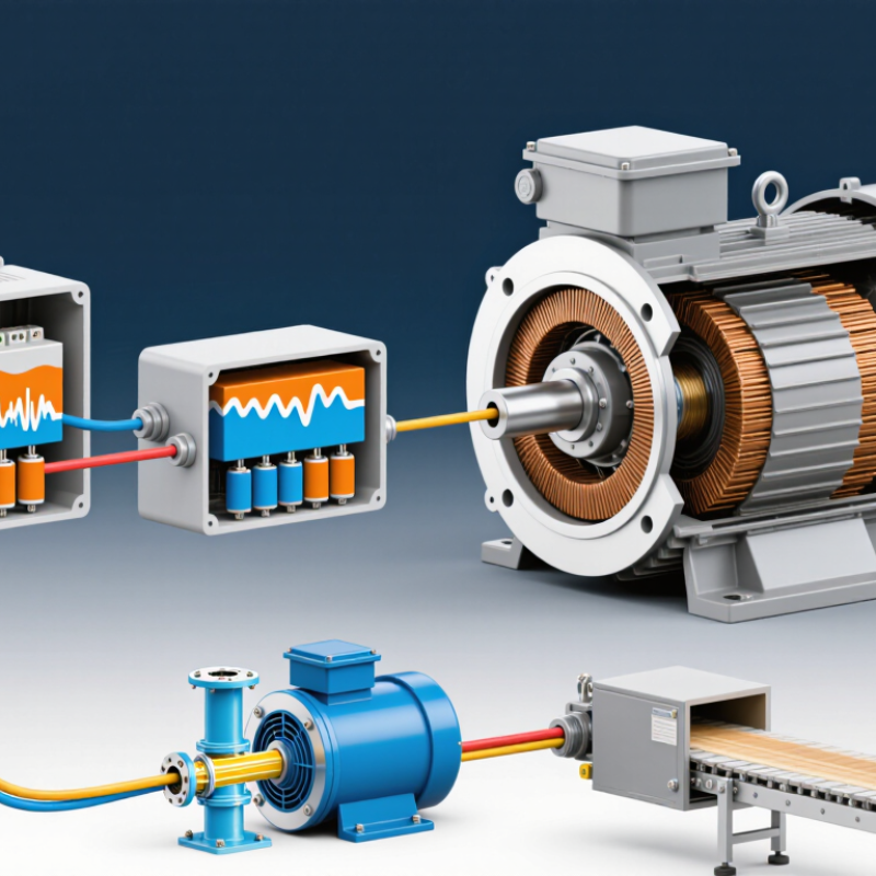
An ac motor vfd controls an AC motor by changing the electrical frequency and voltage supplied to it. This lets equipment adjust its speed to match the work instead of running at one fixed rate. Inside the drive, a rectifier converts incoming AC power into DC. A DC bus smooths and stores that energy briefly. Then an inverter switches the DC into a controlled AC output. The process happens continuously, responding to the drive’s settings and control signals.

That matters. A pump can slow when demand drops, while a conveyor can start gradually instead of jolting into motion. Lower speed may reduce energy use, but the result depends on the load and operating conditions. I would not assume every slower setting saves power. Not always.

A VFD also provides useful control features, such as adjustable acceleration, deceleration, and motor protection. During installation, technicians check the motor nameplate, drive ratings, wiring, and application requirements. They should also consider cooling: a motor’s built-in fan may move less air when the motor runs slowly. Long motor cables and switching effects can introduce additional concerns. These details are easy to overlook.

In practice, setup and commissioning matter as much as the drive itself. Incorrect parameters can cause poor performance, nuisance trips, or excess motor heating. The equipment manual and qualified technical guidance are reliable starting points. Understanding how an AC motor VFD works helps users choose suitable settings, recognize limitations, and ask better questions before changing a system.
What Is an AC Motor VFD and How Does It Work?

Defining an AC Motor Variable Frequency Drive

An AC motor variable frequency drive (VFD) is an electronic controller that adjusts the electrical power supplied to an AC motor. Instead of running the motor at one fixed speed, it changes the power frequency and voltage to influence speed and torque. A typical drive converts incoming AC power to DC, smooths it in a DC bus, then uses electronic switches to produce controlled AC output. That output is commonly pulse-width modulated rather than a smooth sine wave. This matters. Switching can create extra electrical stress and heat, depending on the motor and installation.

For an induction motor, speed generally follows the supply frequency, although load and motor design affect actual shaft speed. A VFD can start a fan gradually, keep a conveyor near a chosen speed, or adjust a pump without relying only on a valve. It does not provide unlimited torque or guarantee energy savings. At low speeds, a motor’s own fan may move too little air for adequate cooling under heavy load. Check the motor nameplate, drive current rating, cable length, and insulation suitability before installation. Real systems are messier. A poorly tuned drive may buzz, hunt, or trip, and finding the cause can require measurements rather than guesswork.

Key Components Inside an AC Motor VFD

An AC motor VFD contains several stages that work together to control motor speed. The rectifier changes incoming AC power into DC. A DC bus, usually with capacitors and sometimes an inductor, smooths and stores that energy. Inside the cabinet, those capacitors can be substantial components, not minor accessories. That matters.

The inverter then switches the DC into an adjustable AC output. Power transistors, often IGBTs, control the output’s frequency and voltage, allowing the motor to run at different speeds. A control board sets the switching pattern and monitors signals from sensors. These may track current, voltage, or temperature. If the motor slows under load, feedback can help the drive adjust its output, within configured limits. Small details count.

Cooling fans or heat sinks carry heat away from the power electronics. Protection circuits can respond to conditions such as overload, overheating, or an unusually high DC-bus voltage. The exact arrangement varies by drive size and design. It is easy to focus on the inverter and overlook wiring, grounding, and airflow; those details affect reliable operation too. Heat is real. A neat diagram does not show every installation problem, so the manual and qualified electrical review still matter.

What Is an AC Motor VFD and How Does It Work? - Key Components Inside an AC Motor VFD

Component What It Does How It Works in the VFD Typical Details
Rectifier Converts incoming AC power into DC power. A diode or controlled-switch bridge rectifies the AC input. A common three-phase design uses a six-pulse bridge. For a conventional rectifier with a capacitor DC bus, the DC voltage is approximately the AC line-to-line RMS voltage multiplied by √2, before load-related effects.
DC Bus Capacitors Stores energy and smooths the rectified DC voltage. Capacitors reduce voltage ripple between the rectifier and inverter, helping provide a steadier DC supply. Capacitance, ripple-current rating, temperature, and operating conditions affect performance and service life.
Precharge Circuit Limits the initial current when the drive is switched on. A resistor or other current-limiting arrangement charges the DC bus capacitors before a bypass device connects the normal power path. Helps reduce inrush current and electrical stress during startup.
Inverter Bridge Converts DC power into variable-frequency, variable-voltage AC for the motor. Power switches, commonly IGBTs or MOSFETs depending on the drive design, turn on and off in a controlled sequence to create three-phase output. Output frequency controls motor speed; output voltage is adjusted with the control strategy to suit the motor and load.
PWM Switching Control Shapes the inverter output into a controllable waveform. Pulse-width modulation varies the timing of the inverter switches. The motor’s inductance helps smooth the resulting current. Switching frequency is selected according to drive design, motor requirements, noise, and thermal limits.
Controller and Gate Drivers Coordinates motor control and safely operates the power switches. The controller calculates switching commands from the speed or torque reference and feedback. Gate drivers translate those commands into signals suitable for the inverter devices. Control methods include volts-per-hertz control and field-oriented control.
Feedback and Protection Sensors Monitor electrical and thermal conditions and help protect the drive. Current, voltage, and temperature measurements are checked by the control system, which can limit output or trip the drive when a fault is detected. Protection functions commonly include overcurrent, overvoltage, undervoltage, and overtemperature monitoring.
Braking Circuit Manages excess energy when a motor decelerates or an overhauling load drives it. Where fitted, a braking transistor can connect a resistor to the DC bus so excess energy is dissipated as heat. Not every VFD includes a braking transistor or resistor; regenerative drives can return energy to the supply instead.
Cooling System Removes heat generated by the power electronics. Heat sinks conduct heat away from semiconductor devices; fans or other cooling methods move heat out of the enclosure. Required cooling depends on drive losses, ambient temperature, installation, and enclosure design.
Keypad and Communication Interfaces Allow users and automation systems to set commands and read drive status. Local controls or communication connections provide speed references, start/stop commands, configuration, and diagnostic information. Available interfaces and protocols vary by VFD model and application.

How a VFD Converts Incoming Electrical Power

What Is an AC Motor VFD and How Does It Work?

An AC motor VFD controls motor speed by changing the electrical power delivered to the motor. Its first job is to process the incoming supply. In many drives, a rectifier uses diodes or controlled switches to convert incoming AC into direct current. The resulting DC is not perfectly steady. Capacitors in the DC bus reduce its ripple and store energy between switching events. Some designs also include an inductor to smooth current.

The inverter then turns that DC into a new AC output. Electronic switches turn on and off in carefully timed patterns, producing pulses that approximate a smooth waveform. Pulse-width modulation adjusts the pulses, while the output frequency sets the motor’s operating speed. Voltage is adjusted too, helping the motor produce useful torque as speed changes. That is the key. A VFD does not simply lower the incoming voltage; it reshapes power for the motor. The picture is useful, but real waveforms are messier, and drive designs vary.

Tips: Check that the VFD’s input matches the available supply and its output suits the motor. Keep cooling vents clear, and follow the drive manual when wiring or changing settings. A quick glance at the display can catch an unexpected frequency or fault.

How Frequency and Voltage Control Motor Speed

What Is an AC Motor VFD and How Does It Work?
How Frequency and Voltage Control Motor Speed

An AC motor VFD controls motor speed by changing the frequency of the electrical power it supplies. Inside the drive, incoming AC power is converted to DC, then switched back into adjustable-frequency AC. The motor’s rotating magnetic field follows that frequency. Lower frequency generally means slower rotation. At 30 hertz, an induction motor may run near half its 60-hertz speed, though slip and load affect the actual shaft speed.

Voltage must change with frequency, too. Below the motor’s rated frequency, a VFD usually reduces voltage in proportion to frequency. This helps maintain magnetic flux and usable torque. Too much voltage at low frequency can overheat the motor. Too little can weaken torque. It is a balance, not a magic dial.

That matters.

At very low speeds, a shaft-mounted fan also moves less air, so the motor may need reduced load or separate cooling. Above the rated frequency, voltage generally cannot rise further. The motor enters field weakening, and available torque falls. Settings depend on the motor nameplate and application; a conveyor and a lightly loaded fan do not behave alike. Real installations may need adjustment after observing motor current, temperature, and performance. A neat calculation can still miss what the machine does under load.

How an AC Motor VFD Controls Speed

A VFD changes the AC supply frequency to control motor speed. For a four-pole motor, synchronous speed is 30 × frequency in rpm. Below the 60 Hz base frequency, the VFD typically increases voltage in proportion to frequency to maintain a roughly constant volts-per-hertz ratio. Actual motor speed is slightly lower under load because of slip.

Operating Modes and Common Applications of AC Motor VFDs

An AC motor VFD controls motor speed by varying the frequency and voltage supplied to the motor. In simple V/f mode, it keeps voltage proportional to frequency, a practical choice for many pumps and fans. Sensorless vector mode estimates motor behavior to improve low-speed torque without an encoder. Closed-loop vector control uses encoder feedback for tighter speed or torque regulation. The right mode depends on the load, not just the motor.

Applications are widespread. The IEA’s Energy-Efficiency Policy Opportunities for Electric Motor-Driven Systems estimates that motor-driven systems use about 45% of global electricity. That figure helps explain why adjustable-speed drives matter in industrial energy management. A variable-torque mode can suit a cooling-tower fan, while constant-torque control is often used for conveyors and mixers. Small details matter.

In a pump room, a VFD can ramp a motor gradually instead of starting it at full speed, reducing mechanical shock. HVAC fans, compressors, machine tools, and water-treatment pumps also use drives to match output to demand. Real installations are messier. Poor parameter settings, undersized drives, or inadequate cooling can undermine performance, so commissioning should include load checks and motor data verification. A drive is not an automatic efficiency fix.

Learn More

Connect with us today to learn more about our industrial automation solutions—and how to commission them for your application.