7 Tips for Choosing Ceramic Laser Reflectors
Choosing the right Ceramic Laser Reflectors is not a cosmetic decision. It affects beam stability, thermal control, operating life, and maintenance costs. In a working laser cavity, a reflector may face intense pulses, repeated heating, and strict alignment tolerances. A small surface defect can become a visible performance problem.
Market reports show why this component deserves closer attention. Grand View Research identifies steady growth in the global laser technology market, driven by medical, industrial, semiconductor, and research applications. MarketsandMarkets also highlights rising demand for higher-power and more reliable laser systems. These reports do not isolate ceramic reflectors perfectly. That limitation matters. Still, they indicate stronger pressure on component quality and thermal performance.
Arthur L. Schawlow, a Nobel-winning laser physicist, once said, “The laser is a solution looking for a problem.” His observation remains useful today. The problem is rarely solved by reflectivity alone. Engineers must compare substrate purity, coating compatibility, thermal expansion, surface finish, aperture size, and supplier consistency. Practical experience suggests that datasheets can hide important differences. Some values are measured under ideal conditions. Real assemblies may experience vibration, contamination, or uneven cooling.
This guide presents seven practical tips for evaluating Ceramic Laser Reflectors. It considers technical specifications, inspection methods, application temperature, coating choices, and long-term reliability. The process is not perfectly simple. Sometimes, the cheapest reflector performs well. Sometimes, it creates expensive alignment work later. Careful selection reduces that uncertainty.
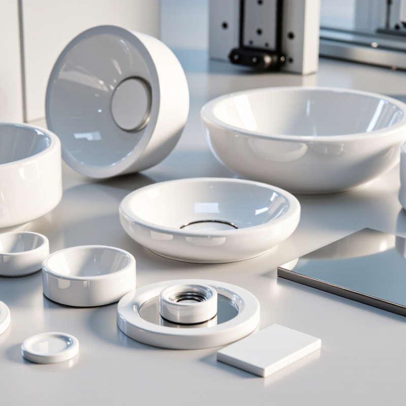
Match Reflector Material to Wavelengths such as 808 nm, 940 nm, and 1064 nm
7 Tips for Choosing Ceramic Laser Reflectors
Match Reflector Material to Wavelengths such as 808 nm, 940 nm, and 1064 nm
Choosing a ceramic laser reflector starts with its working wavelength. A material that performs well at 808 nm may behave differently at 940 nm or 1064 nm. Check measured spectral reflectance, not just a general “high reflectivity” claim. Ask for data across the full operating band.
For 808 nm systems, inspect absorption and thermal stability during continuous operation. At 940 nm, small spectral losses can create noticeable heat in compact cavities. For 1064 nm, verify that the ceramic surface and coating remain efficient at the longer wavelength. Alumina-based ceramics can offer useful thermal strength, but composition, porosity, and surface finish matter greatly.
Then check seven practical details: wavelength range, reflectance, power density, temperature rating, surface roughness, dimensional tolerance, and cleaning resistance. Keep the reflector close to the intended geometry. Even a small gap may reduce optical efficiency. Measure the actual part when possible.
I once trusted a bright white surface too quickly. That was a mistake. Visible brightness does not prove infrared performance. Test samples under realistic pulse width, cooling, and mounting conditions. Also examine edge chipping and coating adhesion after thermal cycling. Published data helps, but production results can differ. Leave room for that uncomfortable possibility.
Compare Alumina Reflectance Above 95% with Diffuse Ceramic Performance
Choosing a ceramic laser reflector starts with one optical question: do you need maximum return or controlled diffusion? In many polished alumina designs, measured reflectance can exceed 95% within a specified wavelength range. That number is useful, but incomplete. Reflectance changes with wavelength, surface finish, incidence angle, contamination, and measurement method. Ask for a test curve, not a single marketing value.
A highly reflective alumina surface sends more pump light back toward the active region. It can improve efficiency when alignment is stable and the cavity geometry is carefully controlled. However, sharp reflections may create hot spots. Small mounting errors can matter. Diffuse ceramic reflectors scatter light across a wider pattern. Their performance may look lower on a directional meter, yet they can provide smoother illumination and better tolerance. This helps when the laser head has uneven spacing or moving components. I have seen a reflector with impressive peak reflectance underperform after fingerprints and poor alignment. Clean handling matters more than expected.
Compare both materials under identical conditions. Use the same wavelength, beam size, angle, and detector geometry. Check performance after thermal cycling, cleaning, and repeated installation. Ask about porosity, density, thickness, and edge strength. A dense ceramic may tolerate heat well, while a fragile edge chips during assembly. Do not ignore that failure mode. I would choose alumina for focused optical recovery and diffuse ceramic for uniform coverage, but this rule needs testing. Prototype both when the design margin is narrow.
7 Tips for Choosing Ceramic Laser Reflectors
Reflectance is a key selection factor for ceramic laser reflectors. The chart compares representative reflectance values for polished alumina and diffuse ceramic surfaces across common laser-related wavelengths.
How to read the chart: Polished alumina maintains reflectance above 95% across the displayed range, while diffuse ceramic provides lower reflectance but can offer more uniform light scattering. Final performance depends on surface finish, porosity, wavelength, angle of incidence, and operating temperature.
Verify Dimensional Tolerance Within ±0.05 mm for Accurate Beam Control
7 Tips for Choosing Ceramic Laser Reflectors
Dimensional tolerance is central to stable beam control. Choose reflectors manufactured within ±0.05 mm on critical surfaces. A small deviation can shift the reflected beam, especially across long optical paths. Check the technical drawing, not only the product description. Confirm which dimensions receive this tolerance. Tip 1: Request a measured inspection report for every critical batch. A certificate builds confidence, but the measurement method matters.
Tip 2: Ask whether dimensions are checked at a controlled temperature. Ceramic expands less than many metals, yet temperature still affects precision. Tip 3: Confirm the reference datums used during inspection. Your mounting fixture must match those datums. Otherwise, an accurate reflector may appear misaligned. Use calibrated gauges, optical comparators, or coordinate measuring equipment when possible. Hand calipers can miss small angular or edge variations.
Tip 4: Inspect the mounting interface for chips, burrs, or uneven contact. Tip 5: Avoid excessive clamping force. Stress can tilt the reflector after installation. Tip 6: Test beam position after tightening, not before. This step is often skipped. In practice, tolerance alone does not guarantee perfect alignment; surface flatness, coating uniformity, and fixture repeatability also matter. I would also leave a small adjustment range in the assembly design. That choice may feel inefficient, but it helps when real-world measurements disagree with the drawing. For demanding systems, record reflector dimensions, temperature, torque, and beam position during acceptance testing.
Assess Porosity, Surface Finish, and Service Temperatures Above 1,000°C
7 Tips for Choosing Ceramic Laser Reflectors
High-temperature laser reflectors need more than a bright, polished surface. ASTM C20 measures apparent porosity, water absorption, and bulk density in fired ceramics. These values reveal hidden pores that can trap moisture, scatter light, and enlarge under thermal stress.
Tip 1: Request tested porosity, not only a visual inspection.
Tip 2: Compare density from the same test method.
Surface finish directly affects reflection and damage resistance. ISO 21254-2 describes laser-induced damage testing, but results depend on wavelength, pulse duration, beam size, and testing atmosphere. A mirror-like finish may perform poorly if polishing leaves scratches or embedded particles.
Tip 3 Match the finish to your wavelength and power density.
Tip 4 Ask for roughness data, inspection methods, and measured damage thresholds.
Service temperatures above 1,000°C require careful thermal planning. ASM Handbook, Volume 4A, reports that alumina melts near 2,050°C, yet practical limits are much lower. Thermal gradients, mounting stress, emissivity, and repeated cycling control real performance.
Tip 5 Evaluate the hottest surface, not the furnace rating.
Tip 6 Check thermal expansion compatibility with the holder.
Tip 7 Require cycling data above your operating temperature.
A useful admission: temperature labels can look precise while hiding major test differences. Test the actual reflector geometry when possible.
